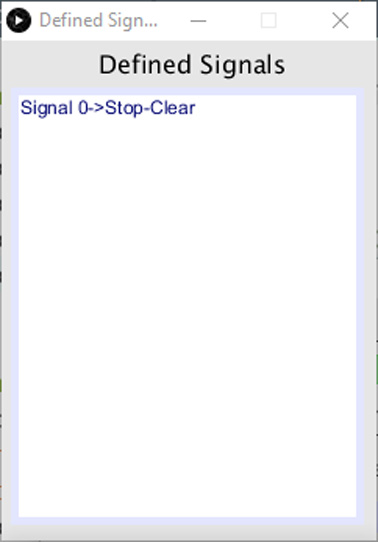
Navigate to a CLIENT and click ![]() to start the Signal Manager. Two windows will open: the Signal Manager and the Signals List.
to start the Signal Manager. Two windows will open: the Signal Manager and the Signals List.
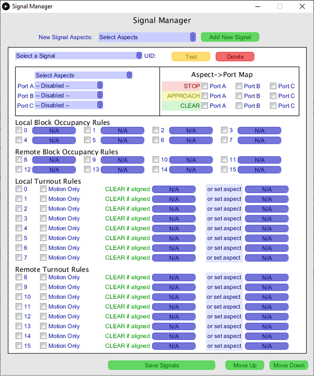
The Signal Manager window comes up with all controls disabled. Adding or loading a signal object will enable controls as explained below.
Creating A Signal #
To create a new signal, select the aspects it will show from the “New Signal Aspects” drop-down list, then click Add new Signal.
Six Signal types, defined by the aspects they can show, are available:
- STOP / OFF
- STOP / CLEAR
- APPROACH / OFF
- STOP / APPROACH / OFF
- APPROACH / CLEAR
- STOP / APPROACH / CLEAR
The LCOS convention is that a signal will show CLEAR or OFF if no condition to set either STOP or APPROACH exists. Those conditions can be block occupancy and/or turnout state.
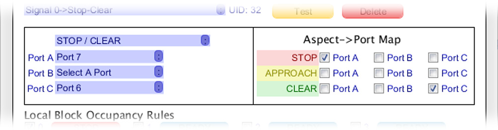
The new signal will be loaded into the edit window. At this point, the controls related to the turnouts and blocks you have previously defined on the node will be enabled. In this example, we are creating a two aspect signal — STOP / CLEAR — on a node that has 4 blocks and 3 turnouts. Accordingly, the rules controls for blocks 0 – 3 and turnouts 0 – 2 are enabled for this signal.
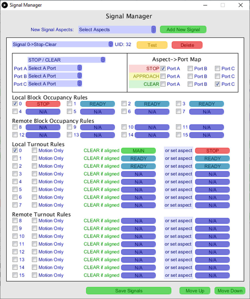
The buttons for enabled layout objects change from N/A to one of these values:
- READY — The object is available, but not yet linked to the signal
- If the object selection checkbox is checked, the button will show STOP, APPROACH or CLEAR — this creates rules for the signal to obey. A more detailed explanation follows below.
Aspect to Port Map #
At the top of the Signal Editor is a section for selecting ports. The first step when creating a new signal is to select the DNOU8 ports to which you have connected the signal.
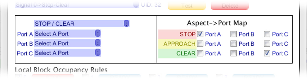
A signal can use up to 3 digital output ports. By default, the system uses Port A for Stop aspects, Port B for Approach and Port C for Clear. Using the default template, the editor will map single ports to signal aspects. Select the ports in use for this signal on the left side.
The checkboxes in the Aspect->Port Map section on the right determine which ports are turned on for a given aspect. By default, the system assumes one port per aspect and sets default port associations: port A for Stop, port B for Approach, and port C for Clear. You can assign any of the three possible ports to any aspect of the Signal.
Some signals may use multiple ports to represent an aspect. Subject to the 3 port limit, LCOS allows you to define how ports are combined and mapped to produce a signal aspect.
In this example, a conventional 2 LED signal is configured to use one port per aspect. Since this is a STOP / CLEAR signal, the APPROACH line is disabled.
Object Checkboxes and Buttons #
To link this signal to a block or a turnout, first select a layout object checkbox. The blue buttons labeled “READY”will change to represent either an aspect (STOP or APPROACH) or, in the case of the button after “CLEAR if aligned”, a turnout alignment selector. When activated, click the buttons repeatedly to cycle between available options; in some cases there may only be one option which cannot be changed.
Continuing with the STOP / CLEAR example, this node monitors 4 local blocks.
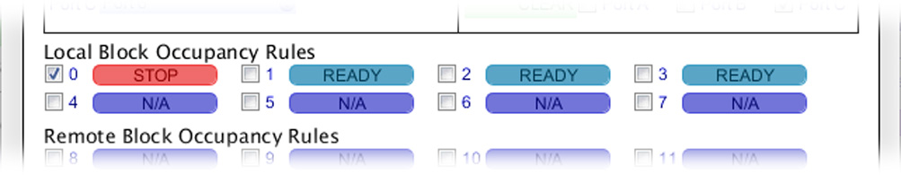
This signal protects block 0 only, so only the checkbox for block 0 is selected. Next to it, the aspect selector is set to STOP. This causes the signal to monitor block 0 and, anytime the block is occupied, the signal must set its aspect to STOP.
The example node also has 3 local turnouts. Two of those turnouts are downstream from and protected by the signal.
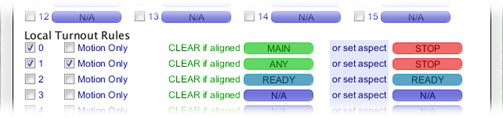
Checkboxes for the two affected turnouts have been selected.
Turnout 0 is set so the points are facing away from the signal. From the perspective of the signal, the turnout can only be transited if it is set to MAIN. In the middle column the safe alignment is selected and, in the right hand column, the aspect to show when the turnout cannot be transited is specified.
Turnout 1 is pointed the opposite way relative to the signal: its points face the signal. In this case, from the perspective of the signal, the turnout can be transited so long as it is not in motion. Accordingly, for this turnout, the “Motion only” checkbox is selected, the safe alignment is automatically set to ANY and the aspect to show when the turnout is moving is set to STOP.
With these settings, the LCOS Signal Object executes a rule that, if written out, would look like this:
IF BLOCK 0 IS OCCUPIED OR
  TURNOUT O IS NOT ALIGNED MAIN OR
  TURNOUT 1 IS MOVING
THEN SET ASPECT TO STOP
ELSE SET ASPECT TO CLEAR


