The DNOU1K Digital Output duinoNode Kit is an easy to assemble electronics kit that can be completed in about 30 minutes.
Tools Required
You will need
- A soldering iron with a small pointed or chiseled tip. Use a low wattage standard iron, or a temperature adjustable soldering station, such as a Hakko FX888.
- Low temperature, rosin core, lead free solder suitable for electronics. Example
- A flush cutting wire cutter. Example
- Self-closing (or cross lock) tweezers. Example
- Alcohol for cleaning soldering residues; denatured alcohol is the most effective, but common isopropyl alcohol will do.
- A chip insertion tool, if you have one.
The Parts
Take a moment to unpack your kit and inspect the contents. Your kit should contain the following parts:
- 1 x DNOU1 PC Board
- 1 x 9 port terminal block
- 3 x 3 port terminal blocks
- 1 x ULN2803 IC, 18-DIP
- 1 x 74HC595 IC, 16-DIP
- 8 x Resistors, 470Ω,
- 2 x Resistors, 2kΩ
- 2 x LED, Green

You may use resistors of different values if you choose. The 8 output resistors are the sized for running standard 20-30 mA LEDs at 12 volts. If you plan to power devices at a different voltage (the DNOU1 supports device voltages from 3.3 to 30 volts), or you want to change the brightness of connected LEDs, you may need to use different output resistors. For inductive loads (such as relays and small motors) you may bridge output resistor locations with jumpers provided the current draw will never exceed .5 amps.
General Instructions & Precautions
- The ICs are static sensitive devices. Work in a low static environment if possible. Make sure to ground yourself while handling the ICs and the board.
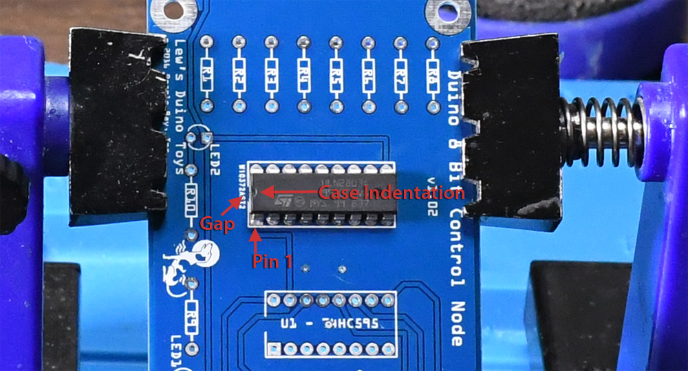
- The ICs and the LEDs are polarized devices. Before soldering, make sure you have the leads in the correct holes. Pin 1 of the ICs goes in the square pad; the anode of each LED also goes into a square pad. Resistors are not polarized and may be placed in any orientation.

- The ICs have a small half-circle indentation on one end of the chip; this marks the end with pin 1. At the IC locations on the board, the rectangular locating outline has a break where the Pin 1 indention should go.
- Work with adequate light and ventilation. Avoid breathing fumes produced by the soldering process. Use adequate protective eye-wear and burn resistant clothing. Use a soldering pad to protect your table/desk.
- Use a secure holding device to hold the PC Board while you insert and solder parts. Use self-closing (cross lock) tweezers to hold parts while soldering.
- Low temperature soldering works best with a “wet” tip. Clean the hot tip with a wet sponge and metal cleaning mesh. Put a little solder on the tip of the iron (just enough to make it “wet” — wipe off any excess), touch the wet part of the iron to the part, then apply enough solder to cover the pad, fill the hole and create a gentle slopped joint. Keeping the tip wet, move from pad to pad applying solder as you go. The iron should touch the part no more than 3 – 5 seconds. If something goes wrong, remove the iron and let the parts cool for a minute before trying again.
- Sometimes with very thin rosin core solder wire there are tiny sections where rosin is missing or inadequate. You’ll know you’ve hit that when the solder melts but refuses to flow onto the board and tends to ball up. You’ll need to remove the failed solder from the board & part, then try clipping a few millimeters off the solder wire; usually that will get past that bad core and restore normal soldering.
Assembly
Secure the board with a PC Board holder or other method.

Insert the ULN2803 IC into the holes where shown. Note the orientation of the Pin 1 mark on the case.
If you do not have a chip insertion tool, insert the pins on one side of the IC into the corresponding holes. Then, using your fingers to press on the case/pins on the opposite side, put just enough pressure on the IC to flex without damaging the inserted pins and insert the opposite row into their respective holes. Use cross lock tweezers to hold the chip tightly against the board.

Turn the board upside down and solder 18 pins.

Turn the board right side up and, using the same techniques as before, insert the 74HC595 IC into the holes where shown. Again, note the orientation of the Pin 1 mark on the case and use cross lock tweezers to secure the part to the board.

Turn the board over and solder 16 pins.

Now insert and solder the LEDs and the 2kΩ resistors. The long lead of an LED is the anode — inserted it into the hole with the square pad. Bend the leads on the bottom of the board to hold the parts in place while soldering. Flush cut the excess leads after soldering.

Next, insert and solder the 8 output resistors, bending the leads on the bottom of the board to hold them in place.

Solder the resistors, then flush cut the excess leads.

The last parts to install are the terminal blocks. These are “rising cage” terminal blocks, providing superior wire hold across a range of wire gauges. Before installing the blocks, inspect them and use a screw driver to lower the cage (turning the screw to the left) and fully open the terminals. Note that the terminals are shipped by the manufacturer in a “closed” state which looks “open” because the cage is at the top of its travel without any wire.
Insert and solder the 9 port terminal block.

Finally, insert the 3 port terminal blocks on the other end and solder in place. If you prefer, you can replace any 3 port terminal block with a pin header using the same pitch: 2.54mm/.1″.

Clean any solder flux residues with alcohol, and you are done!

For instructions on using the assembled boards, see DNOU1 Instructions
Updated: 8/7/2021